
Understanding Ladder Logic PLC Graphical Programming language Guide in Industrial Automation Solution
What is the difference between ladder logic and structured text?, Why Ladder Logic Is Widely Used in Automation? and What software is used for ladder logic programming?
 Explore Automation Solutions
Shop Process Control Equipment
Ladder Logic Programming Guide: A Practical Introduction for PLC Engineers
Programmable Logic Controllers (PLCs) are the backbone of modern industrial automation, and ladder logic remains the most widely used programming language for controlling machines and industrial processes. Although today’s PLC platforms support several IEC 61131-3 programming languages, ladder logic continues to dominate manufacturing because it is intuitive, reliable, and easy for electricians, technicians, and engineers to troubleshoot.
Whether you’re an automation engineer, maintenance technician, controls integrator, or engineering student, understanding ladder logic is an essential skill. From simple motor starters to complex manufacturing systems with hundreds of I/O points, ladder logic provides a visual programming method that mirrors traditional electrical relay circuits while offering the flexibility of modern software.
This guide explains the fundamentals of ladder logic programming, how PLCs execute ladder programs, common programming instructions, practical design techniques, troubleshooting methods, and industry best practices. By the end, you’ll have a solid understanding of how ladder logic works and how to build reliable PLC programs for industrial applications.
What Is Ladder Logic?
Ladder logic is a graphical programming language defined by the IEC 61131-3 standard for programmable logic controllers. It represents electrical control circuits using symbols that resemble the rungs of a ladder, making it familiar to electricians and maintenance personnel who have experience with relay-based control systems.
Instead of writing lines of programming code, engineers create logic diagrams using contacts, coils, timers, counters, comparison instructions, and mathematical functions. Each rung represents one logical operation, and the PLC evaluates these rungs sequentially during every scan cycle.
The language earned its name because the diagram resembles a ladder:
Two vertical rails represent the power supply.
Horizontal rungs contain the program logic.
Each rung performs a specific control function.
Although the visual appearance is similar to relay wiring diagrams, ladder logic is software. This means engineers can modify, expand, or troubleshoot a program without physically rewiring the control panel.
For engineers beginning their PLC journey, understanding ladder logic is often easier than learning traditional programming languages because it closely follows the logic of electrical control circuits.
Why Ladder Logic Remains the Industry Standard
Despite advances in automation software and object-oriented programming, ladder logic continues to be the preferred programming language in many industries.
Several factors explain its longevity.
Easy for Maintenance Teams to Understand
Industrial facilities operate around the clock, and downtime can be expensive. When equipment fails, maintenance technicians need to diagnose problems quickly.
Because ladder diagrams closely resemble electrical schematics, technicians can immediately understand the sequence of operations without extensive software training.
Fast Troubleshooting
Modern PLC software allows engineers to monitor ladder logic in real time.
During online monitoring, energized contacts change color, timers display accumulated values, and outputs show their operating status. This visibility dramatically reduces troubleshooting time.
Widely Supported
Nearly every major PLC manufacturer supports ladder logic, including:
Siemens
Allen-Bradley
Mitsubishi Electric
Omron
Schneider Electric
ABB
Delta Electronics
Although software interfaces differ, the programming concepts remain largely consistent across platforms.
Ideal for Discrete Manufacturing
Ladder logic excels in applications such as:
Conveyor systems
Packaging equipment
Material handling
Machine safety
Assembly lines
Pump control
Motor control
These applications rely heavily on binary decisions, making ladder logic an excellent fit.
How PLCs Execute Ladder Logic
Understanding how a PLC executes a ladder program is just as important as learning the programming symbols. Every PLC operates continuously using a repetitive process called the scan cycle.
Reading Inputs
The PLC first reads the status of every input device.
Examples include:
Pushbuttons
Selector switches
Proximity sensors
Pressure switches
Limit switches
Photoelectric sensors
The PLC stores this information in memory before executing the program.
Executing the Program
Next, the PLC evaluates each ladder rung from:
Left to right
Top to bottom
Every instruction is processed logically until all rungs have been evaluated. This sequential execution is known as the program scan.
Updating Outputs
After processing the logic, the PLC updates its outputs.
Outputs may include:
Motor starters
Solenoid valves
Indicator lights
Relays
Variable frequency drives
Servo systems
The output image is then written to the physical devices.
Repeating the Scan
Once complete, the PLC immediately starts another scan. Modern controllers may execute thousands of scans every second depending on processor speed and program complexity.
Basic Ladder Logic Components
Every ladder program consists of a collection of standard instructions. Understanding these instructions is the foundation of PLC programming.
Normally Open (NO) Contact
A normally open contact allows logic to pass when the referenced bit is ON.
Typical uses include:
Start buttons
Sensor detection
Internal memory bits
Normally Closed (NC) Contact
A normally closed contact allows logic to pass when the referenced bit is OFF.
Applications include:
Emergency stop monitoring
Safety interlocks
Fault detection
Output Coil
The output coil energizes an output when all conditions on the rung are satisfied.
Examples:
Start a conveyor
Energize a relay
Turn on a warning light
Timers
Timers delay events or control process timing.
Common timer types include:
On-delay (TON)
Off-delay (TOF)
Retentive timer (RTO)
Industrial examples include delaying motor starts, sequencing conveyors, or controlling dwell times in packaging equipment.
Counters
Counters keep track of repetitive events.
Typical applications include:
Counting products
Tracking machine cycles
Monitoring pallet quantities
Counters are commonly classified as:
Count Up (CTU)
Count Down (CTD)
Comparison Instructions
Comparison instructions evaluate numerical values.
Examples include:
Greater than
Less than
Equal to
Not equal
These instructions are widely used in temperature control, pressure monitoring, and production quality verification.
Essential Ladder Logic Programming Techniques
Writing ladder logic is about more than placing contacts and coils on a screen. Well-designed programs are structured, readable, and easy to maintain.
Start/Stop Motor Circuits
One of the first programs every PLC engineer learns is the three-wire motor control circuit.
This circuit typically includes:
Start pushbutton
Stop pushbutton
Seal-in contact
Motor output
The seal-in contact keeps the motor running after the operator releases the Start button until the Stop button is pressed or a fault occurs.
Interlocks
Interlocks prevent unsafe or conflicting operations.
Examples include preventing:
Forward and reverse motor commands at the same time
Two valves opening simultaneously
Conveyor startup when safety gates are open
Proper interlocking is critical for equipment protection and operator safety.
State-Based Programming
For complex machines, state-based programming provides a structured way to control sequences.
Instead of relying on numerous interdependent outputs, the machine transitions through defined operating states such as:
Idle
Ready
Running
Fault
Maintenance
This approach improves readability and simplifies troubleshooting.
Alarm Management
Effective alarm logic should provide clear, actionable information rather than overwhelming operators with unnecessary notifications.
Best practices include:
Prioritize critical alarms.
Avoid duplicate alarms.
Include fault descriptions.
Log alarm history for analysis.
Ladder Logic Best Practices
Experienced controls engineers follow proven programming standards to improve maintainability and reduce commissioning time.
Some of the most important recommendations include:
Use descriptive tag names instead of generic addresses.
Group related logic into functional sections.
Comment every major routine.
Keep individual rungs simple.
Eliminate duplicate logic.
Standardize naming conventions across projects.
Test every safety function thoroughly.
Simulate programs before deployment whenever possible.
Well-organized programs are easier to troubleshoot and significantly reduce long-term maintenance costs.
Common Ladder Logic Programming Mistakes
Even experienced programmers occasionally introduce logic errors.
Some of the most common mistakes include:
Overusing internal memory bits
Creating circular logic
Forgetting to reset timers or counters
Ignoring scan sequence effects
Using duplicate output coils
Writing overly complex rungs
Poor documentation
Avoiding these issues improves program reliability and simplifies future modifications.
Real-World Applications of Ladder Logic
Ladder logic is used in virtually every industrial sector because it provides dependable, deterministic control.
Manufacturing
Factories use ladder logic to control:
Assembly lines
Robotic cells
Packaging machines
Material handling systems
Food and Beverage
Applications include:
Filling machines
Conveyor systems
Mixing operations
CIP systems
Water and Wastewater
Municipal facilities rely on ladder logic for:
Pump stations
Lift stations
Chemical dosing
Filtration systems
Oil and Gas
Automation systems control:
Pump sequencing
Pipeline monitoring
Compressor stations
Emergency shutdown systems
Power Generation
Power plants use ladder logic to automate auxiliary equipment, cooling systems, fuel handling, and electrical distribution.
- Industrial Automation Fundamentals
- Industrial Communication Protocols
- Industrial Instrumentation Control
- Industrial Sensors & Measurement
- Motion and Process Control
- PLC Programming & Controllers
- SCADA and DCS Systems
- Servo Motors and Motor Drives
Frequently Asked Questions
What is ladder logic programming?
Ladder logic programming is a graphical programming language used to develop control programs for programmable logic controllers (PLCs). It resembles electrical relay diagrams, making it easy for engineers and technicians to design, understand, and troubleshoot industrial control systems.
Why is ladder logic still widely used?
Ladder logic remains popular because it is intuitive, reliable, and supported by nearly every major PLC manufacturer. It is particularly effective for discrete manufacturing applications and simplifies maintenance by presenting logic in a familiar visual format.
What is the difference between ladder logic and structured text?
Ladder logic is a graphical language best suited for discrete control and troubleshooting, whereas Structured Text is a text-based language similar to Pascal that is often used for complex calculations, algorithms, and data manipulation.
Is ladder logic difficult to learn?
Most electricians, technicians, and engineers find ladder logic relatively easy to learn because it closely resembles traditional electrical schematics. With a solid understanding of relay logic and PLC fundamentals, beginners can quickly build simple control programs.
What software is used for ladder logic programming?
The software depends on the PLC manufacturer. Examples include Studio 5000 Logix Designer for Allen-Bradley, TIA Portal for Siemens, GX Works3 for Mitsubishi Electric, Sysmac Studio for Omron, EcoStruxure Control Expert for Schneider Electric, and Automation Builder for ABB.
What industries use ladder logic programming?
Ladder logic is used extensively in manufacturing, food and beverage, automotive, water and wastewater treatment, oil and gas, mining, pharmaceuticals, logistics, and power generation because of its reliability and ease of maintenance.
Can ladder logic be used with Industry 4.0 technologies?
Yes. Although Industry 4.0 introduces technologies such as IIoT, edge computing, cloud analytics, and artificial intelligence, ladder logic remains the core control language inside many PLCs. Modern controllers integrate ladder logic with advanced communication protocols and data platforms, allowing traditional control strategies to coexist with smart manufacturing initiatives.
Ladder logic has remained the foundation of PLC programming for more than five decades because it combines simplicity, reliability, and maintainability. While automation technologies continue to evolve with Industry 4.0, digital twins, and artificial intelligence, the principles of ladder logic still underpin countless industrial control systems around the world.
Whether you are programming a simple motor starter or commissioning a fully automated production line, mastering ladder logic will give you the practical skills needed to design safe, efficient, and scalable automation solutions. By understanding the PLC scan cycle, using structured programming practices, documenting your logic clearly, and following industry standards, you can develop control systems that are easier to commission, troubleshoot, and expand as operational requirements change. For PLC engineers, ladder logic is more than just a programming language—it is a fundamental engineering discipline that continues to drive modern industrial automation.
Check Our Comprehensive Automation Brands Get Latest Industrial Automation NewsYour One-Stop Source for Reliable Industrial Automation & Process Control Equipment
Access trusted process control equipment, expert support, and fast sourcing—all in one place.
-
AC Drives 18,169 Products
-
Circuit Breakers2,227 Products
-
Contactors567 Products
-
Control Valve238 Products
-

Counters78 Products
-

Encoder117 Products
-
Fanuc Main Board1,376 Products
-
Flow Transmitter (Flow meter)552 Products
-
HMI/Touch Screen594 Products
-
Industrial Device Servers125 Products
-
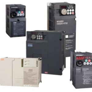
Inverter914 Products
-

Network/Signal2 Products
-

Others4,501 Products
-
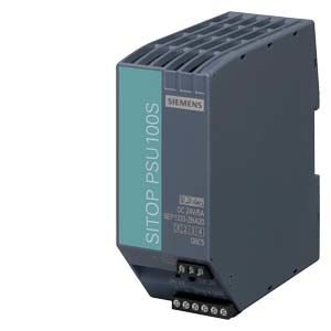
Power Supply220 Products
-
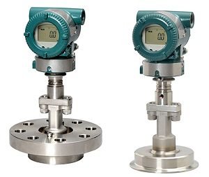
Pressure Transmitter146 Products
-
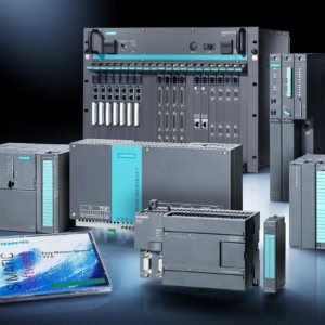
Programmable Logic Controller (PLC)6,295 Products
-
Relay927 Products
-
Sensor2,221 Products
-
Servo Motors & Motor Drives5,037 Products
-
Switch897 Products
-

Timer93 Products
-

Uncategorized1,154 Products
-
Variable Frequency Drives (VFD)255 Products
-
Yokogawa Remote Indicators16 Products

Leave a Reply